Patent examples
Below are examples of PCT / international patents that we have drafted and filed:
Railway coupling patent:
Patent summary: This invention relates to a coupling adaptor. More specifically, the invention relates to a coupling adaptor for coupling railway vehicles having different types of coupling systems. The coupling adaptor includes a first coupling formation being correspondingly engageable with a first type of coupler, a second coupling formation being correspondingly engageable with a second type of coupler, and a buffer for impacting similar buffer formations on the railway vehicles during coupling. This enables, through the coupling adaptor, a first railway vehicle fitted with the first type of coupler to couple to a second railway vehicle fitted with the second type of coupler.
Click on image to view whole patent document
Door lock patent:
Patent summary: The invention refers to a slip clutch mechanism ( 10) for a door (52) including: a first engaging member (20) for connecting a control handle (64) and a lock mechanism (56), a second engaging member(30) for connecting to a slave handle (68), one or more of the engaging members (20, 30) being at least partially resiliency deformable such that the first and second engaging members (20, 30) are resiliently deformable with respect to one another between a coupled condition, wherein the first and second engaging members (20, 30) are correspondingly engageable to move in unison so as to transfer rotational movement of the slave handle (68) to the lock mechanism (56), and a decoupled condition, wherein the first and second engaging members (20, 30), through relative deformation, slip with respect to one another thereby preventing transfer of rotational movement of the slave handle (68) to the lock mechanism (56), the coupled condition arising in the event of a force difference between a force applied to the slave handle (68) and a force applied to the control handle (64) being less than a predefined threshold, and the decoupled condition arising in the event of a force difference between a force applied to the slave handle (68) and a force applied to the control handle (64) being greater than the predefined threshold, such that the locking mechanism (56) is capable of being actuated by the control handle (64) at all times and by the slave handle (68) only in the event giving rise to the coupled condition.
Click on image to view whole patent document
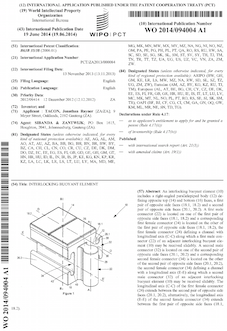
Desiccating toilet patent:
Patent summary: A waste disposal unit (10) for desiccating solid waste includes a housing (12) with a disc (14) rotatably mounted therein. The housing (12) defines an inlet aperture (18) that permits solid and liquid waste material to be deposited into the housing (12) and onto the disc (14). Liquid waste material flows by the influence of gravity off the disc (14) into a liquids receptacle at or near the centre of the disc (14). A spiral scraper (16) is located above the disc (14) and fixed against rotation relative to the housing (12). Rotation of the disc (14) relative to the scraper (16) causes solid waste material to spiral towards the outer perimeter of the disc (14) and into a solids receptacle.
Click on image to view whole patent document

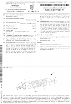
Conveyor belt patent:
Patent summary: A conveyor belt section (10) capable of bending vertically and horizontally includes a base (12) and side walls (14, 16) extending anguiarly from opposing sides of the base ( 12) to form a channel (18), wherein the belt section ( 10) is corrugated with at least two alternating peaks (20) and troughs (22) extending continuously across the side walls ( 1 4, 16) and base (12).
Click on image to view whole patent document
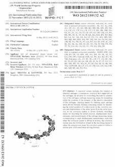
Conveyor system patent:
Patent summary: A conveyor system (10) includes two tracked or wheeled carriages (12); a continuous conveyor belt (16) supported on the carriages (12); an actuator (18) for controlling the relative orientation of the carriages (12); carriage measuring means for measuring either the position of the actuator (18) or the relative orientation of the carriages (12); steering means for steering each carriage (12) while driven forward; distance measuring means for measuring the initial position of a select point on the conveyor system (10) and displacement of the select point from the initial position as the conveyor system (10) is driven forward; recording means for recording the initial position, displacement measurements, and measurements of the carriage measuring means corresponding to each displacement measurement, such that when the conveyor system (10) is driven in reverse, the conveyor system (10) uses the information stored in the recording means to adjust the actuator (18) and cause the conveyor system (10) to follow a similar path it followed when driving forward.
Click on image to view whole patent document
Idler roller patent:
Patent summary: This invention relates to an idler. More specifically, the invention relates to any type of tracking idlers or pulleys (also known as trainer idlers or pulleys) typically used in the application of conveyors for the purposes of guiding a travelling conveyor belt to follow a central path. The idler, for guiding a travelling conveyor belt to that the belt follows a central path, includes a support axle (14), a steering roller (12), a pivot means and a castellated formation of alternating ridges (20) and grooves (22) having specific ranges of, amongst other, groove width to enable portions of the conveyor belt to sag there into for the purposes of increasing the steering action of the idler on the conveyor belt.
Click on image to view whole patent document
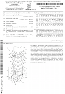
Conveyor feeder patent:
Patent summary: This invention relates to a feeder. More specifically, the invention relates to a secure feeder for feeding material onto a conveyor belt enclosed in a pipe, generally known as a pipe conveyor, preventing access to the material being transported thereby. The feeder includes a container, a flow regulating member and a flow restricting member. The container defines a loading end for receiving material and a discharge end for discharging material into the conveyor belt. In use, the flow regulating member regulates the flow of material through the discharge end of the container while the flow restricting member restricts the flow of material deposited on the conveyor belt to an upstream-to-downstream direction thereby preventing the backflow of material in an opposite downstream-to-upstream direction. Furthermore, the flow restricting member comprises a free end positionable in use in contact or close proximity with the conveyor belt.
Click on image to view whole patent document
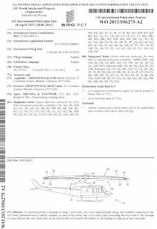
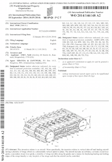
Aircraft patent:
Patent summary: An aircraft (10) includes a fuselage (12) or wing; a rotor mast (14); two rotors (16a, 16b) spaced axiaily along, and rotatabiy connected to the rotor mast; permanent and/or electro magnets (18) on each of the rotors (16a, 16b) and a rotor mast (14) joint connecting the rotor mast to the fuselage (12) or wing, wherein the rotor mast joint (20), in use, permits the rotor mast to relative to the fuselage or wing in at least one plane.
Click on image to view whole patent document
Aerofoil wing patent:
Patent summary: The present disclosure relates to a wing. More specifically, aspects of the invention relate to a variable shaped wing movable incrementally between a neutral configuration and a deformed configuration, wherein the wing takes a reflexed camber aerofoil section shape in the deformed configuration. The wing includes a first aerofoil segment and a second aerofoil segment having ends connected or fixed to one another at opposing neutral leading and trailing edges and spaced apart from one another along their lengths across a neutral mean camber line extending between the neutral leading and trailing edges to form a neutral aerofoil section of the wing. One or more actuators deform the wing between the neutral aerofoil section and a reflexed camber aerofoil section, with the first and second aerofoil segments being resilient to bias the wing towards an initial at rest aerofoil section.
Click on image to view whole patent document
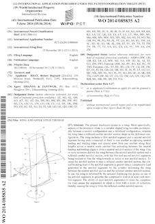
Aircraft wing patent:
Patent summary: This invention relates to an aircraft. More specifically, the invention relates to vertical take-off and landing aircraft having a plurality of wings (18) orbital in a substantially vertical operative plane. The aircraft includes an airframe (12), a primary closed loop guide(20A, 20B), a secondary closed loop guide(22A, 22B), a plurality of wings (18) movable along the guides and a means for displacing leading and trailing edges of the wings thereby to vary the pitch of the wings such that the aircraft can be controlled.
Click on image to view whole patent document
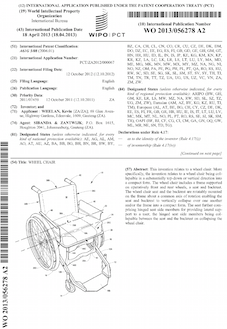
Wheelchair patent:
Patent summary: This invention relates to a wheel chair. More specifically, the invention relates to a wheel chair being collapsible in a substantially top-down or vertical direction into a compact form. The wheel chair includes a frame supported on operatively front and rear wheels, a seat and backrest. The wheel chair seat and the backrest are rotatably mounted on the frame about a common axis of rotation enabling the seat and backrest to vertically collapse over one another and/or the frame into a compact form. The seat further comprising hinged seat side members for providing lateral support to a user, the hinged seat side members being collapsible between the seat and the backrest on collapsing the wheel chair.
Click on image to view whole patent document
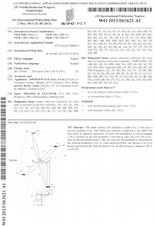
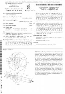
Wind turbine patent:
Patent summary: The wind turbine (10) includes a shaft (14), a first and a second propeller (16a, 16b) which are rotatably connected to the shaft (14) and rotate in opposite directions. At least one permanent or electro-magnet ( 18) is located on the first propeller ( 16a) and at least one coil (18) is located on the second propeller ( 16b). By that way the generator is integrated in the rotating propellers (16a, b). Each propeller-blade can include a tab (22) projecting towards the other propeller (16a, b) and carrying a magnet ( 18) or a coil (18).
Click on image to view whole patent document
Timing system patent:
Patent summary: A timing system that includes a glyph associated with an object to be timed and at least one camera for capturing images of the glyph or associated object. A computer generates a virtual line, associates the virtual line with at least one of the images, and determines when the glyph or associated object intersects, crosses or has crossed the virtual line. A database records the identity of the glyph and the time that the glyph or associated object intersected or crossed the virtual line. The invention also relates to a related method for determining the time a glyph or object associated therewith passes a predetermined point or line.
Click on image to view whole patent document
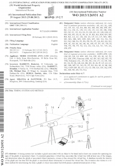
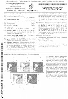
Image processing patent:
Patent summary: A method of generating and processing images with variable light conditions includes the steps of: (i) capturing a first image using a sensor or camera having a first quality parameter setting (e.g. ISO sensitivity setting, the shutter speed setting, the aperture setting and/or the sensitivity setting); (ii) capturing a second image using, a sensor or camera having a second quality parameter setting, which second quality parameter setting is different to the first quality parameter setting; (iii) creating a composite image using a portion of the first image and a portion of the second image, without overlap of the image portions; and (iv) performing an image processing technique on the composite image.
Click on image to view whole patent document
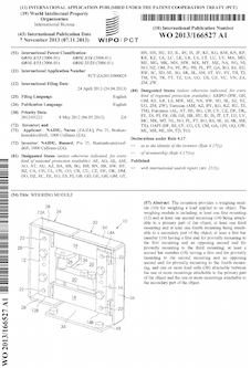
Scale patent:
Patent summary: The invention provides a weighing module (10) for weighing a load applied to an object. The weighing module is including: at least one first mounting (12) and at least one second mounting (14) being attachable to a primary part of the object; at least one third mounting and at least one fourth mounting being attachable to a secondary part of the object; at least a first bar member (16) having a first end for pivotally mounting to the first mounting and an opposing second end for pivotally mounting to the third mounting; at least a second bar member (18) having a first end for pivotally mounting to the second mounting and an opposing second end for pivotally mounting to the fourth mounting, and one or more load cells (20) attachable between the one or more mountings attachable to the primary part of the object and the one or more mountings attachable to the secondary part of the object.
Click on image to view whole patent document
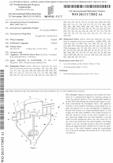
Separator patent:
Patent summary: Separator apparatus and method for treatment of a contaminated liquid by injecting air/gas to lower the specific gravity of the contaminated liquid by at least 20% and rotating the contaminated liquid to separate contaminants by centrifugal forces. The separator includes a swirl chamber defining a longitudinal axis; at least one injector for, in use, introducing: (i) liquid entrained with air/gas; (ii) air/gas-entrained liquid; or (iii) air/gas, into the swirl chamber; a first outlet located at or near the operative bottom of the swirl chamber for, in use, removing sludge from the swirl chamber; a second outlet located operatively above the first outlet for, in use, removing liquid from the swirl chamber; circulating means to, in use, circulate liquid in the swirl chamber; and an elongate body that extends from or near the operative top of the swirl chamber, along the longitudinal axis of the swirl chamber, beyond the level of the at least one injector.
Click on image to view whole patent document
Alcohol reducing process patent:
Patent summary: The present invention refers to a process for reducing alcohol in a fermented beverage comprising (i) pre-heating a fermented beverage feedstock to a temperature between 40°C und 60°C, (ii) introducing said feedstock into the upper section of a distillation column operating at a pressure between 5kPa and SOkPa and a temperature between 40°C und 80°C, (iii) subjecting the feedstock, as it flows down the column, to alcohol vapour rising up the column, thereby stripping aromatics from the feedstock to yield an aromatic vapour. The aromatics are condensed. The fermented beverage is introduced into the upper section of a second distillation column operating at a pressure between 5kPa and 50 kPa and a temperature between 45 °C and 85°C and is subjected to steam/low-concentration alcohol vapour. The resulting alcohol vapour is transferred to a rectifier and is concentrated there. The fermented beverage is discharged from the second distillation column and mixed with the condensed aromatics.
Click on image to view whole patent document
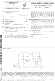
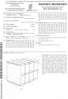
Golf club patent:
Patent summary: This invention relates to a golf club, More specifically, the invention relates to a putter (10) having a striking face (18A) with a variable loft angle. The golf club includes a shaft (12) and a club head (14) connected to a first end of the shaft (12). The club head (14) comprises a body member (16), a striking member (18) defining a striking face (18A) set at a predetermined loft and a bridging member (20) connected at opposite ends to the body member (16) and the striking member (18) across a space (26) defined therebetween. The bridging member (20), the body member (16) and the striking member (18) jointly form one integral body, wherein the height (h) of the bridging member (20) is less than the height (H) fo the striking face (1 8A) enabling movement of the striking member (18) relative to the body member (16) thereby to vary the loft angle of the striking face (18A) between the predetermined loft angle and a secondary loft angle. Movement of the striking member (18) relative to the body member (16) is enable through deformation of the bridging member (20), the body member (16) and/or the striking member (18) relative to one another.
Click on image to view whole patent document
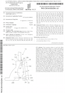
Fencing system patent:
Patent summary: A modular fencing system includes a first profile comprising a web (18) and a flange (20) that extends transversely from one end of the web in a first direction. The web defines a countersunk portion (24) that extends towards the first direction, a first aperture (26) in the countersunk portion (24), and a second aperture (28). A second connecting means (40) sized to pass through the second aperture (28), secures the first profile to an adjacent profile in back-to-back arrangement. A bracket (16) is securable to the web (18) via a first connecting means (40) comprising a neck sized to pass through the first aperture (26) and a head sized to be received within the countersunk portion (24). The bracket (16) is shaped to extend towards the flange (20) and defines an edge extending substantially along the flange (20), which edge defines at least two teeth (36) for capturing at least one elongate segment of a fence panel between: (i) the teeth (36); and (ii) the flange (20) and/or web (18) to secure the fence panel (14) in place relative to the first profile.
Click on image to view whole patent document
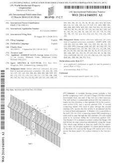
Storage cabinet patent:
Patent summary: A cabinet storage system includes a first cabinet, a second cabinet and at least two wheels on the operative base of each of the first and second cabinets. The cabinets are secured to each other by: an upper connector comprising a first connector member that defines a track, which first connector member is connected to the operative upper half of the first cabinet; and a second connector member that is at least partially locatable within and slideable along the track, which second connector member is secured to the operative upper half of the second cabinet, such that, when connected to each other, relative slidable movement of the cabinets is guided and limited by the upper connector.
Click on image to view whole patent document
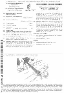
Parking system patent:
Patent summary: A parking monitoring system includes a device having a unique identifier; a reader that, when located in close proximity to the device, reads the unique identifier of the device; the device being located within a parking bay such that, when the parking bay is occupied by a vehicle, access to the device by the reader is restricted, thereby restricting the reader’s ability to read the unique identifier of the device; and a database that stores the status of the parking bays; and the steps of: instructing a user via the reader within a predetermined time period to read the unique identifier of the device in a bay that, according to the database, is vacant; and locating the reader within such predetermined time period in close proximity to such device to read the unique identifier of such device and thereby confirm the vacant status of such bay on the database.
Click on image to view whole patent document
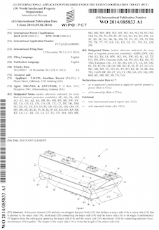
Can patent:
Patent summary: A can end (10) includes a substantially planar portion (12) and a first frangible line (18) on the substantially planar portion (12). The first frangible line (18) divides the substantially planar portion (i2) into: a first cover (20) substantially bounded by the first frangible line (18); and a residual portion (22). The can end (10) further includes: means (24) for separating the first cover (20) from the residual portion (22) along the first frangible line (18) to create an aperture therebetween; and a second cover (i4) secured to the residual portion (22). Such that, the second cover (14) at least partially closes the aperture when the first cover (20) is partially separated from the residual portion (22).
Click on image to view whole patent document
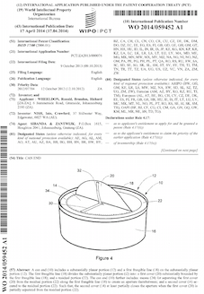
Drilling clamp patent:
Patent summary: Apparatus (10) for breaking threaded pipe connections (12) includes a housing ring (16) that is, in use, rotatably connected to a frame (14), the housing ring (16) defining an aperture (10) for, in use, receiving a pipe section therethrough. At least three cams (20) are pivotally connected to the housing ring (16). A guide ring (18) is rotatable relative to the ring (16) between an open position in which the cams (20) are, in use, radially spaced from a pipe section extending therebetween and a clamped position in which the cams (20), in use, engage with and clamp the pipe section. The guide ring (18) defines at least three ramps (24), each ramp (24) causing a corresponding cam (20) to ride up the ramp (24), pivot and protrude radially inwards as the guide ring (18) is rotated from the open position to the clamped position; and includes at least three fingers (26) that bear against the cams (20) to cause the cams (20) to pivot and retract radially outwards as the guide (18) is rotated from the clamped position to the open position. Such that, at least a portion of each ramp (24) and corresponding finger (26) forms a recess defined by the guide ring (18) that receives at least a portion of the corresponding cam (20) therein when the guide ring (18) is in the open position.
Click on image to view whole patent document
Pump float patent:
Patent summary: A buoyant element (10) includes an elongate buoyant body (12) that defines a major side (14), a minor side (16) that is parallel to the major side (14), axial ends (20) connecting the major side (14) and the minor side (16) at an angle of substantially 45 degrees from the orthogonal spanning the major side (14) and the minor side (16) and means (18) for connecting adjacent buoyant elements (10) together. The length of the major side (14) is twice the length of the minor side (16).
Click on image to view whole patent document
Floating walkway patent:
Patent summary: An interlocking buoyant element (10) includes a right-angled parallelepiped body (12) defining opposite top (14) and bottom (16) faces, a first pair of opposite side faces (18.1, 18.2) and a second pair of opposite side faces (20.1, 20.2). A first male connector (22) is located on one of the first pair of opposite side faces (18.1, 18.2) and a corresponding first female connector (24) is located on the other of the first pair of opposite side faces (18.1, 18.2), the first female connector (24) defining a channel with longitudinal axis (C-C) along which a first male connector (22) of an adjacent interlocking buoyant element (10) may be received slidably. A second male connector (32) is located on one of the second pair of opposite side faces (20.1, 20.2) and a corresponding second female connector (34) is located on the other of the second pair of opposite side faces (20.1, 20.2), the second female connector (34) defining a channel with a longitudinal axis (E-E) along which a second male connector (32) of an adjacent interlocking buoyant element (10) may be received slidably. The longitudinal axis (C-C) of the first female connector (24) extends between the second pair of opposite side faces (20.1, 20.2), alternatively, the longitudinal axis (E-E) of the second female connector (34) extends between the first pair of opposite side faces (18.1, 18.2).
Click on image to view whole patent document
Syringe patent:
Patent summary: A syringe includes a monolithic barrel (12) being divided into two bore portions, a first bore portion (22) extending from the needle adapter partially towards the second axial end and a second bore portion (24) extending from the first bore portion to the second axial end, wherein the first bore portion is circular in cross section and the second bore portion has a cross sectional shape that at least partially extends beyond the radius of the first bore portion. The syringe includes a plunger (14) sized to fit within and move along the longitudinal axis of the first bore portion. A plunger rod (16) extends along the longitudinal axis of the monolithic barrel, the plunger rod including a first array of notches and/or protuberances (30) along at least a portion of its length. The syringe includes an insert (18) sized to fit wholly within the second bore portion, the insert defining a bore through which the plunger rod extends and including a first finger (36) extending into the bore defined by the insert for, in use, engaging the first array of notches and/or protuberances on the plunger rod.
Click on image to view whole patent document
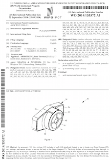
Syringe cover patent:
Patent summary: An accessory (10) for a syringe (12) includes: a body (14) sized and shaped in use to locate over finger flanges (22) on a syringe; and means, in use, to secure the body to the finger flanges (22). The body defines a bore extending there through. A plunger rod (16) including a first array of notches and/or protuberances (44) along at least a portion of its length is received within the bore defined by the body. Located within the bore defined by the body is an insert (18) that defines a bore through which the plunger rod, in use, extends. The insert (18) also includes a first finger (48) extending into the bore defined by the insert for, in use, engaging the first array of notches and/or protuberances (44) on the plunger rod (16).
Click on image to view whole patent document
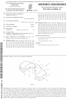
Slidable syringe cover patent:
Patent summary: An accessory (10) for a syringe (12) includes a body (14) sized and shaped in use to locate either over finger flanges (24) on a syringe or to a barrel of a syringe. Securing means (16), in use, secure the body to either the finger flanges or the barrel (22) of a syringe. The body defines a primary bay (38) for receiving a plunger rod (26) therein, the primary bay: (i) includes at least one nipple (18) extending from the body into the primary bay, the nipple forming a constriction along the primary bay through which the plunger rod must, in use, pass before being captured within the primary bay with a portion of the body engaging the array of notches and/or protuberances (34) on the plunger rod; and (ii) is sized and shaped such that, in use, when the body is secured to finger flanges or barrel of a syringe and a plunger rod is received and captured within the primary bay, the longitudinal axis of the plunger rod is aligned with the longitudinal axis of the syringe barrel.
Click on image to view whole patent document
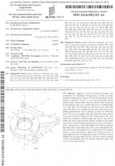
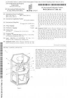
Sorting machine patent:
Patent summary: This invention relates to a sorting apparatus (10). More specifically, the invention relates to a high throughput sorting apparatus (10), particularly suited for diamond sorting. The sorting apparatus (10) includes a dispenser (12) for dispensing a material, a diffuser (14), at least one sensor ( 16) and at least one deflector (18). The diffuser (14) in use comprises a receiving region ( 14A) for receiving material from the dispenser (12), a downwardly sloping surface (1413) radiating from and about the receiving region (14A) for diffusing material as it travels along the diffuser (14) and a continuous rim (14C) over which the material is discharged from the diffuser (14). In use, where the sensor (16) senses that a property of the material discharged from the diffuser (14) matches a predefined property, the deflector (18) is triggered to deflect the material into a collection bin.
Click on image to view whole patent document
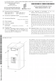
Key safe patent:
Patent summary: A key safe (10) includes a main container (14) defining an access port (20), an antechamber (16) and a primary hook (22) located within the antechamber (16). The antechamber (16) is movable between a first position in which a user is permitted access thereto and to the primary hook (22) from outside the main container (14) via the access port (20), and a second position in which the user is not permitted access to either the antechamber (16) or the primary hook (22) from outside the main container (14). The key safe (10) further includes a plurality of secondary hooks (26) located within the main container (14), which secondary hooks (26) are not directly accessible to a user. In use, transport means (18) transport keys between the primary hook (22) and a secondary hook (26) when the antechamber (16) is in the second position.
Click on image to view whole patent document
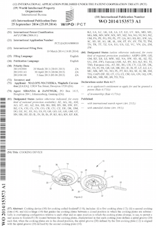
Sausage cooker patent:
Patent summary: Cooking device (10) for cooking coiled foodstuff (1 8), includes: (i) a first cooking plate (12); (ii) a second cooking plate (14); and (iii) a hinge (16) that guides the cooking plates between a closed position in which the cooking plates are substantially in overlapping configuration relative to each other and an open position in which the cooking plates diverge, in use, to permit a user access to foodstuff (18) located between the cooking plates, characterized in that each cooking plate defines a spiral groove (20) such that, when the cooking plates are in the closed position, the spiral groove (20) defined by the first cooking plate (12) is aligned with the spiral groove (20) defined by the second cooking plate (14).
Click on image to view whole patent document
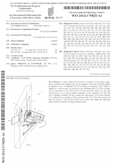
Solar cooker patent:
Patent summary: A solar cooker (10) includes a container (14) having a transparent operative top surface (22) and an operative side wall (24) that defines an aperture (26). A dwelling wall (12) defines an aperture (20), which is framed by a wall mount (16) secured to the dwelling wall (12). The container (14) is connected to the wall mount (16) and movably relative to the wall mount (16) so as to permit proper alignment of the container (14) with the sun. A flexible conduit (18) may connect the wall mount (16) to the container (14). Alternatively, a portion of the container side wall (124) and a portion of the wall mount (1 16) may be curved so as to nest one within the other and permit relative slidable movement therebetween.
Click on image to view whole patent document
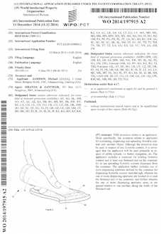
Butter applicator patent:
Patent summary: THIS invention relates to an applicator. More specifically, the invention relates to applicator for containing, dispensing and spreading flowable content onto another object. Although the invention may be used in respect of any flowable content, it is envisaged that the applicator will be used primarily in respect of edible spreads, i.e. butter, margarine, etc. The applicator includes a container for holding flowable content and at least one flattened end on the container for in use spreading flowable content dispensed from the container. The applicator further includes one or more dispensing apertures defined by the container for dispensing flowable content therethrough, wherein the one or more dispensing apertures are located at or near the flattened end of the container, and further wherein the one or more dispensing apertures span, or are spaced relative to one another, along the width of the flattened end.
Click on image to view whole patent document
Light patent:
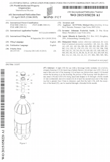
Patent summary: A light (10) for use with a beverage bottle includes: (i) a hollow, elongate housing (12) for receiving a battery therein; (ii) at least one LED (16) at or near a first axis end of the housing; (iii) at least one photovoltaic panel (14) located within the housing or on the housing, the portion of the housing with the photovoltaic panel (14) and LED (16) being steed and shaped to fit through a bottle mouth 22 mm in diameter; and (iv) a head (22) at or near the second axial end of the housing that is greater than 22mm in diameter, such that the light (10), with the exception of the head (22), can be inserted through a threaded bottle mouth.
Click on image to view whole patent document
Armco patent:
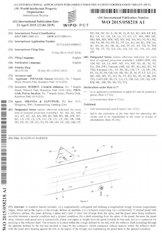
Patent summary: A roadway barrier includes: (i) a longitudinally corrugated rail defining a longitudinal trough between longitudinal ridges, which rail in the region of the trough, defines an aperture: (ii) a reflector comprising: (a) a substantially V-shaped panel with a reflective surface, the panel defining a spine and a pair of arms that diverge from the spine, and the panel arms being resiliently movable between a neutral condition and a splayed condition; (b) a shaft extending from the spine of the panel, between the panel arms, wherein each panel arm is substantially planar and tapers in height from the spine towards its free end; and (c) a connector for securing to the reflector shaft. The reflector is located within the trough defined by the rail, with the reflector shaft extending through the aperture defined by the rail and secured in place by the connector, which connector induces tension within the reflector shaft, with the panel arms bearing against the rail, in the region of the trough, and maintaining the panel arms in the splayed condition.
Click on image to view whole patent document
Surge protection patent:
Patent summary: This invention relates to a surge protection device (10). More specifically, the invention relates to a surge protection device for protecting electronic equipment against damage from high voltage spikes induced in power, television/satellite and/or telecommunication lines arising mainly from localised lightning strikes. The surge protection device Includes a housing (12) with a plurality of input and output sockets(14, 16) for connecting to inputs (i.e. power, TV antenna, etc.) and outputs (i.e. electronic equipment): respectively. The device further includes a switch (18) for electrically connecting and disconnecting the input sockets (14) from the output sockets (16), the switch (18) comprising stationary contacts (20) and movable contacts (22) located on a movable switch arm (18A), the movable arm (18A) being movable between a connected state wherein the stationary (20) and movable contacts(22) are in electrical connection with one another, and a disconnected state, wherein the stationary (20) and movable contacts (22) are displaced from one another to form an air gap there between. The device (10) further includes a motor (26) for moving the movable switch arm (18A), a controller for actuating operation of the motor (26) and a detector for detecting; an event thereby to trigger operation of the controller.
Click on image to view whole patent document